MEGAN HAINES
LIGHTING/ELECTRICAL
ECCLES THEATER
SALT LAKE CITY, UTAH
Building statistics

Building Name
Location and Site
Dates of Construction
Occupancy/Function
Size
Number of Stories
Cost Info
Project Delivery Method
Eccles Theater
131 S. Main Street, Salt Lake City, Utah
March 2012-October 2016
Theater, Office
285,000 SF
1 below ground, 4 above ground
Total Estimate: Hard Cost $82 million
Design-Bid-Build
Design Team
Architect on Record
Interior Architect
Mechanical
Lighting
Electrical
Construction
Structural
HKS Architects
Pelli Clarke Pelli Architects
Buro Happold Consulting Engineer
Cline Bettridge Bernstein Lighting Design
Buro Happold Consulting Engineer
Swisher Garfield Traub Development
Thornton-Tomasetti Engineers
& Reaveley Engineers + Associates

Systems
Architecture
Building Enclosure
The major focal point of the design is bringing Broadway to Salt Lake City and the theater becomes the centerpiece. This is where no expense or consideration was spared. Still following IBC 2012 in Utah, the building conformed to these standards. The building is zoned within a region called Salt Lake. There are no historical requirements for this building.
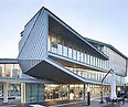
The façade heavily relies on windows that are all specified as two layers of 1/4” safety glass separated by an air space and sealed acoustically and air tight with rubber seals where the air space contains a desiccant material to prevent misting. Other materials on the façade include some areas of brick and on the front end there are frames of steel to hold everything into place.
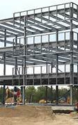
Construction

The façade heavily relies on windows that are all specified as two layers of 1/4” safety glass separated by an air space and sealed acoustically and air tight with rubber seals where the air space contains a desiccant material to prevent misting. Other materials on the façade include some areas of brick and on the front end there are frames of steel to hold everything into place.
Electrical

The project delivery method is design-bid-build. Two large cranes were used to assemble the building. Proper demolition and waste management were enforced so that new construction could occur. LEED was a heavy determining factor when it came to any material or building method as noted in the specifications.
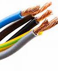
There are 5 major electrical zones that are supplied within the entire building. They break down by location and use of each zone. Rocky Mountain Power, the building’s utility company, is a low cost distributer compared to average values not only nationally but also within the state of Utah. Supplied at 277/480V, the building breaks down to 120/208V to supply to smaller loads within the building. The smaller loads include lighting, receptacles, and theater equipment. In case of a power outage, there is an emergency generator that is a 300 kW diesel that is rated to last for eight hours.
Lighting
There is a lot of specialty lighting equipment used for shows, which operate on a digital-network lighting control system called Electronic Theater Lighting Controls (ETC). The system was the only approved lighting and control system on the project because it includes a computer-based software that provides control, configuration, monitoring, and reports.
The ETC system incorporates:
-
Lighting Control Server
-
Light management computer
-
Lighting control system computer software
-
Factory assembled dimming and switching
-
Touch Panel control stations
-
Low Voltage Control Stations and Control Interfaces and Sensors
-
Permanently Installed Occupancy/Vacancy sensors and Power Packs
-
Permanently Installed photocells
The system is expected to have an operational life of 10 years given the ambient temperature is between 32 and 104 degrees Fahrenheit. It can withstand a discharge without impairment of performance if subjected to 15,000 Volts per IEC 801-2. It also has a warranty of 2 years.

Mechanical
Air Handling Units
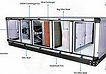
10 custom Temtrol units, which range from 8,000 CFM to 40,000 CFM. All are 460V 3 phase at 60 HZ.
Chiller

2 McQuay 250 ton centrifugal units. The flow rate of evaporation is 400 GPM and has an initial temperature of 54 degrees Fahrenheit and leaves at 42 degrees Fahrenheit. The condenser has a flow rate of 750 GPM and has an initial temperature of 76 degrees Fahrenheit and leaves at 86 degrees Fahrenheit. The working fluid is water and has a head loss of 15 FT. The efficiency of each unit is 0.518 kW/ton and operates at 460 V, 3 phase, at 60 HZ.
Cooling Tower

2 towers located on the roof with the fan airflow of 50 and 790 CFM. The ambient temperature is 66 degrees Fahrenheit and a flow rate 633.2 CFM. The working fluid is water with an initial temperature of 86 degrees Fahrenheit and final temperature of 76 degrees Fahrenheit. Each motor is 10 HP, 1750 RPM and operates at 120 V, single phase, and at 60 HZ.
Expansion Tank
Nine in the project that are within 6 of the 10 air handling units and 2 within the mechanical room. The two in the mechanical use water as the working fluid while the air handling units use 40 percent P GLY H. The two larger tanks within the mechanical room are 119 and 57 gallons while the rest within the air-handling units are each 37 gallons.

Hydronic Boiler

Two Lochinvar Crest units that condenses using natural gas as a fuel source. An input load of 4,000,000 BTU/hr produces an output load of 3,720,000 BTU/hr at a flow rate of 252 GPM. The temperature enters at 110 degrees and leaves at 140 degrees Fahrenheit using water as the working fluid. System has a head loss of 15 FT. Each unit is a 208V, 3 phase and operates at 60 HZ.
VRF Units
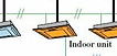
Broken into 5 systems. Most of the indoor units are wall mounted but a few ducted where difficult. All operate on 208-230V on a single phase.
Specialty Systems
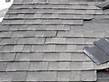
Roofing on the building heavily considers acoustics and is a single-ply membrane. Roof channels, aprons and corner joiners were made of #16 gauge galvanized steel formed to prevent a direct path of air and sound leakage.
Structural
The structural system follows the 2012 IBC. Basic wind speed for this part of the country is 120 mph with an exposure type B. Two foot mat concrete is used for the footing of the building sits on a concrete frame. For slab reinforcing, 3.5 inches of slab sits on top of steel floor decking that is 3 inches deep. For the first couple of floors a non-post tensioned system is used where the slab is about 3/4 of a foot throughout the building. On floors 3 to the roof, a post tensioned concrete system is used where the thickness is mostly a foot. The roof incorporates a 3.5 inch slab which is held up using a rectilinear system that has equidistant beams spanning the full latitudinal distance of the building and W27x84 cross beams.
Telecommunications
The telecommunication system is comprised of the security system, sensors, and fire alarms . Security cameras extend CAT-6 cables to the IT room network rack via a cable tray. There were two types of occupancy sensors that were specified on the project. Both were standalone, non-networked, ultrasonic sensors. The mounting of the two sensors was ceiling and wall switch mounted. The differences between the two are that the ceiling mounted is class 2, low voltage and incorporates a power pack that runs on DC current for power supply. The wall switch is simply connected into the switch. The fire alarm system operates on a low voltage system hooking to a central alarm system.
Transportation

There are 5 elevators located within the building and they vary on how many floors each reaches. There are only two that extend the whole way through the building to the roof. Each elevator sits on a 3" slab on top of a gravel structural fill. The shell utilizes reinforced CMU for its guide rail bracketing at a maximum distance of 10'6". The minimum lighting requirement is 19 fc at the top of the hoist way and 1 fc at the elevator pit floor. Each elevator is hooked up to the standby generator in case of emergency power outage. The minimum outside air required for each elevator is 3.5%.